HELLO THERE!!!
Welcome to the 3rd part of the series. Today I will introduce to you guys on a powerful app, blynk. You can download the app on playstore to your smartphone. After downloading and installing the app, you need to sign up for the app to use it. Next, you need to download the blynk library for arduino from here: http://www.blynk.cc/getting-started/ . You can also try the beginner experiment there.The objective of this experiment is to control LED the brightness by using blynk to LED connected to Arduino.
Ok, now for the hardware, we need:
1.Arduino UNO
2.LED
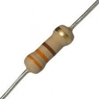
3.Resistor (preferably 330 ohms)
For the software:
1. Arduino IDE
2.Blynk app in smartphone
The circuit assembly is exactly the same as the blink project:
 |
| The blink circuit assembly |
As usual, I am going to divide the project into two parts, The arduino sketch and the Blynk app. Firstly, let's set up the button and slider in blynk app:
1. Create a new project. You will be given an authentication code. The code will be later used in the Arduino to connect to Blynk app.
2. Go to widget box and add a slider.
3.Set up the slider. Insert your LED pin into the PIN box. You can set min- max value at the slider settings.
Now, for the Arduino IDE:
1. After downloading the blynk library for arduino, open the Arduino_Serial_USB sketch. The sketch will be as follows:
#include <SoftwareSerial.h>
SoftwareSerial SwSerial(2, 3); // RX, TX
#define BLYNK_PRINT SwSerial
#include <BlynkSimpleSerial.h>
// You should get Auth Token in the Blynk App.
// Go to the Project Settings (nut icon).
char auth[] = "YourAuthToken";
void setup()
{
SwSerial.begin(9600);
Blynk.begin(auth);
// Default baud rate is 9600. You could specify it like this:
//Blynk.begin(auth, 57600);
}
void loop()
{
Blynk.run();
}
2.Enter the authentication code and upload to arduino
3.Next run the blynk-ser batch file under Blynk_vxxx--->Blynk---->scripts.
4. Enter your arduino port into the blynk-ser.
5. Now test it using blynk!!!!


Comments
Post a Comment