
Mixing Color with RGB LED!!

HELLO THERE!!!

   Hi everybody!! How are you guys? This week, I am going to share with you guys a fun experiment that I did during the weekends. The objective of this experiment is to use the RGB LED to output different colors. Without wasting further time, let's get into the experiment!!


HARDWARE:
1.Arduino UNO

2. 3 Potentiometer

3. RGB LED ( I used the Keyes RGB LED)

SOFTWARE:
1.Arduino IDE

CIRCUIT ASSEMBLY:

 By referring to the image below:

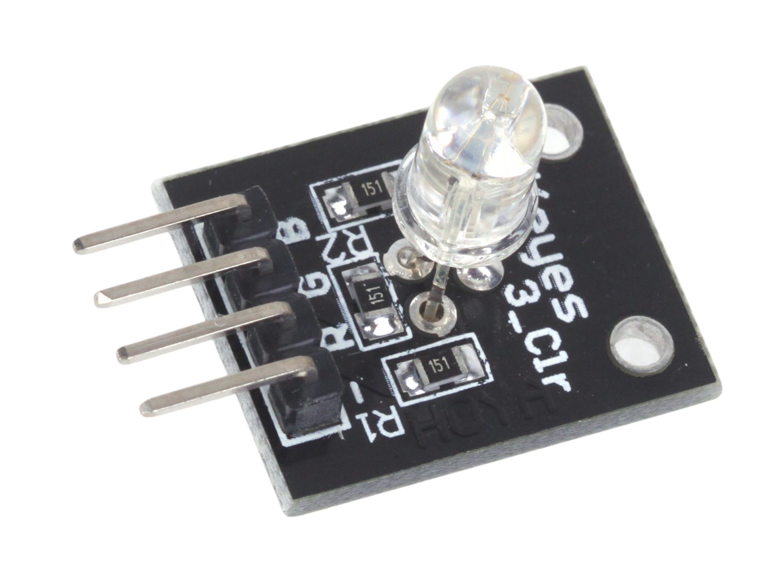
The RGB LED has 4 pins, 1 GND, 1 pin each for the color red, green and blue.

RGB LED                      ----------> ARDUINO
 GND(- sign of the pin)                  GND
R,G,B                                              Any Digital pin(I used pin 9,10 and 11)

The potentiometer consists of 3 pins, the middle pin is for analog reading and the other two pins is for GND and 5V.

Just in case, if some of you guys are not using the RGB LED model that I am using, you can also refer to the circuit assembly below. The circuit assembly below shows the common cathode RGB LED pin connection to arduino:


If you are using the common anode RGB LED, just switch the GND pin of the RGB LED to 5V pin.

CODING THE ARDUINO:

int potpin = A0;// pins for the potentiometer
int potpin1 = A1;
int potpin2 = A2;

int redPin = 11;//pin for the RGB LED
int greenPin = 10;
int bluePin = 9;

int val=0;// initialize variables for analog reading
int val1=0;
int val2=0;

int ov=0;
int ov1=0;
int ov2=0;

void setup(){
Serial.begin(9600);//serial communication at 9600 bps
  pinMode(redPin, OUTPUT);//declaring the pins as output
  pinMode(greenPin, OUTPUT);
  pinMode(bluePin, OUTPUT);  
}

void loop() {
  val = analogRead (potpin); //read potentiometer value
  val1 = analogRead (potpin1); 
  val2 = analogRead (potpin2); 
ov = map(val, 0, 1023, 0, 255);//mapping the val: this means that the val value of 0
//is mapped to value 0 and the val value of 1023 is mapped to 255
ov1 = map(val1, 0, 1023, 0, 255);
ov2 = map(val2, 0, 1023, 0, 255);


     setColor(ov, ov1, ov2);  //set the color of the RGB LED
}


void setColor(int red, int green, int blue)
{

  analogWrite(redPin, red);//matching the variable to the value redPin=red and etc
  analogWrite(greenPin, green);
  analogWrite(bluePin, blue);  
}


Upload the code to Arduino and adjust the potentiometer values to get different color on the RGB LED.

I had made the experiment and the result is shown as below:


Well, that's all from me this week, guys. I hope to see you guys in the next post. Till then, HAPPY TINKERING!!


Comments

Popular posts from this blog

Arduino and Multi Function Shield: Pots,LEDs and buzzers

HELLO THERE!!!!!    How are you guys? I hope everyone is fine and in good mood always. This week, I continue my tinkerings with the Multi Function Shield. In this experiment, I used the potentiometer in the shield to control the LEDs in the shield. Without further wasting time, let's jump in straight to the experiment!! HARDWARE 1.ARDUINO UNO  2.MULTI-FUNCTION SHIELD SOFTWARE: 1. ARDUINO IDE CIRCUIT ASSEMBLY    The circuit assembly is fairly simple. Just attach the multi function shield on top of Arduino properly. Please attach the shield properly as failure to do so would cause the shield  not to function as intended. CODING THE ARDUINO: Let's refer to the multi-function shield image below: Referring to the image of the shield, it can be seen that the potentiometer (blue object near buttons) is connected to pin A0 (analog 0)     int pot = A0; //declaring the pot and led pins int l1 = 13; int l2

Arduino Beginner Experiments: Arduino and Light Blocking Sensor

HELLO THERE!!!     How are you guys? I hope everyone is fine and in a good mood always. This week, I would like to share with you guys my experiment on Arduino and Light Blocking Sensor. The objective of this experiment is to receive feedback from the sensor ( Digital and Analog) What is Light Blocking Sensor?      A linear hall sensor is a type of sensor which responds when the sensor is blocked out from light. The sensor is different for LDR's as LDR's responds to the amount of light it received while the light blocking sensor responds if the light is blocked out or not from the sensor.It can be used for both digital and analog measurements. HARDWARE: 1.Arduino UNO 2. Light Blocking Sensor SOFTWARE: 1.Arduino IDE CIRCUIT ASSEMBLY   Let's refer to the image of the blocking sensor below: The Connection of the Sensor to the Arduino is shown below: SENSOR  ----->       ARDUINO Signal      ------>     Any Analog/Digital pin

Arduino Tinkering : Controlling multiple LED with multiple potentiometers

HELLO THERE!!!!            How are you guys? I hope everyone is fine and well always. For this week's post, I would like to share with you guys a simple tinkering on Arduino, LED, and potentiometers. The objective of the experiment is to light up different amount of LED's with different intensity by controlling two potentiometers. Before starting, of course, we need to know what items are needed. The items needed are: 1. Arduino UNO   2. 4 to 5 LEDs 3. 2 Potentiometers The software used in this experiment is: 1. Arduino IDE. Now that all the hardware and software are obtained, let's go to the schematics of the circuit. The circuit is quite simple actually. The long legs of the LED's were connected to PWM pins while the shorter legs were connected to ground. The potentiometers however have three legs. The middle leg is connected to the analog pins (A0, A1) while the other two legs were connected to 5V and GND respectively. Don't w