HELLO THERE!!!!
 2. LED

How are you guys? I hope everyone is fine and good always. This week, I would like to share with you guys on controlling LED by using Arduino and Processing. Last month, I have shown nearly similar experiment but by using keyboard. The output of this experiment will be the on/off of LED when mouse is clicked. I had done this experiment quite a long time ago and decided to share with you guys.
Ok, first things first, the items needed for this experiment.
Hardware:
1. Arduino UNO( or any Arduino)

3.330 ohm resistor recommended


Software:
1.Arduino IDE
2. Processing IDE
Ok now, that's done, let's see how does the circuit is assembled. The circuit assembly is similar to the blink experiment.
Pretty easy right? Now, let's get going to the code. The code is divided into two part, Arduino and Processing. Now the Arduino code:
char val; //data received from the serial port
int led=13;//the led is in pin 13
void setup(){//arduino setup part,here we connect from processing to arduino
pinMode(led,OUTPUT);//set led as output
Serial.begin(9600);//begin serial communication at 9600 bit per second(speed)
}
void loop(){//where data from processing comes in,arduino decides what to do with the data and the led
if(Serial.available())
{
val = Serial.read(); //if data from serial present, store it in val
}
if (val == '1'){
digitalWrite(led,HIGH); //if val =1 led on
}
else{
digitalWrite(led,LOW); //if val = 0 led off
}
delay(10); //delay 10 milliseconds to avoid overloading
}
The processing code:
import processing.serial.*;//importing files,instructions from serial
Serial port; //creating a class from the serial header
void setup() //the setup part
{
size(400,400);//make our canvas size 400x400 pixels
port = new Serial(this, "COM16", 9600);
}
void draw(){ //this is like the looping part in arduino
if (mousePressed == true)
{
port.write('1');
println("1"); //if mouse is pressed, then led on arduino should be on and 1 will be printed
}else
{ port.write('0'); //send a 0 to arduino,turn off led
}
}
Upload the arduino code and run the processing code. A canvas will be formed from the processing code. Click on the canvas to turn on the LED.
Ok now, that's done, let's see how does the circuit is assembled. The circuit assembly is similar to the blink experiment.
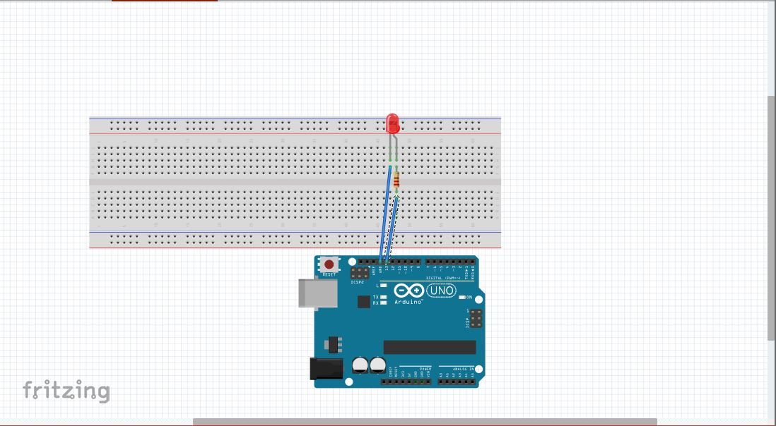 |
| The assembly of the circuit |
Pretty easy right? Now, let's get going to the code. The code is divided into two part, Arduino and Processing. Now the Arduino code:
char val; //data received from the serial port
int led=13;//the led is in pin 13
void setup(){//arduino setup part,here we connect from processing to arduino
pinMode(led,OUTPUT);//set led as output
Serial.begin(9600);//begin serial communication at 9600 bit per second(speed)
}
void loop(){//where data from processing comes in,arduino decides what to do with the data and the led
if(Serial.available())
{
val = Serial.read(); //if data from serial present, store it in val
}
if (val == '1'){
digitalWrite(led,HIGH); //if val =1 led on
}
else{
digitalWrite(led,LOW); //if val = 0 led off
}
delay(10); //delay 10 milliseconds to avoid overloading
}
The processing code:
import processing.serial.*;//importing files,instructions from serial
Serial port; //creating a class from the serial header
void setup() //the setup part
{
size(400,400);//make our canvas size 400x400 pixels
port = new Serial(this, "COM16", 9600);
}
void draw(){ //this is like the looping part in arduino
if (mousePressed == true)
{
port.write('1');
println("1"); //if mouse is pressed, then led on arduino should be on and 1 will be printed
}else
{ port.write('0'); //send a 0 to arduino,turn off led
}
}
Upload the arduino code and run the processing code. A canvas will be formed from the processing code. Click on the canvas to turn on the LED.
Comments
Post a Comment